M7.2: The rear DB-19, fitted with a 3D print
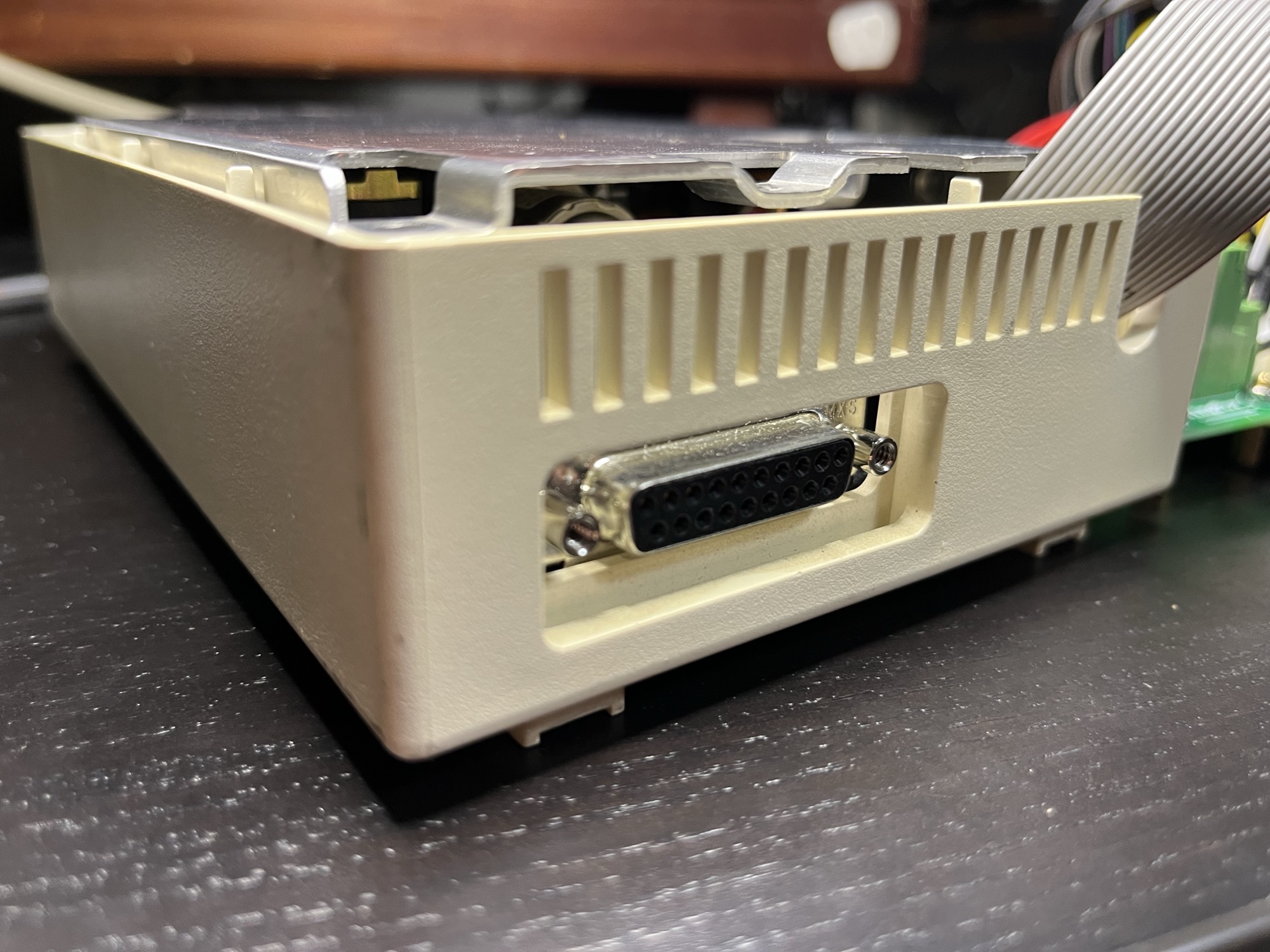
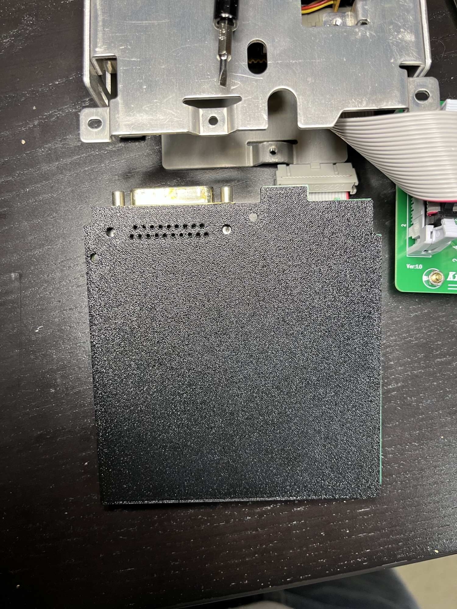
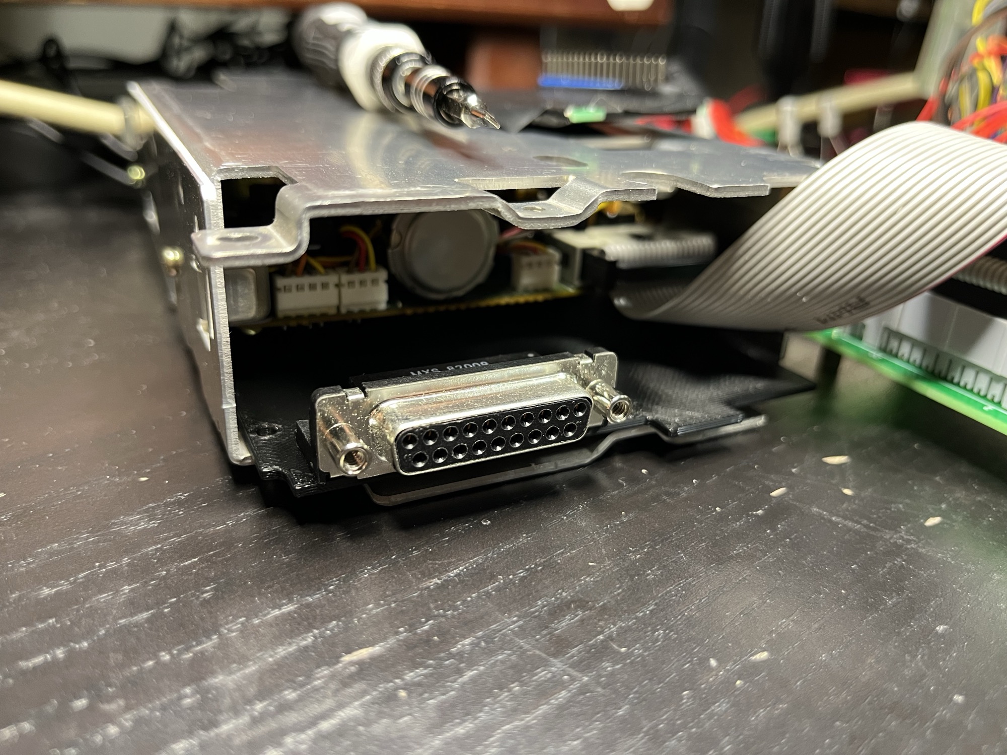
The rear DB-19 is on the board now. I printed the outline again with the holes for it, pushed a salvaged connector into the print and set it in the drive. The board locks went through, the print sat on the mounting points, and with the case on, the D-shell sits in the rear opening. That was the first print for this part.
KiCad has no DB-19
The connector is a salvaged female right-angle DB-19 with forked board locks, marked MXS 82009 / 8251-9246. KiCad’s stock D-sub footprints skip 19 pins.
If you need a DB-19 footprint in KiCad: the pin pitch is the same as every D-sub, 2.77 mm along a row and 2.84 mm between rows. A DB-19 is the stock socket pattern with 10 pins in one row and 9 in the other, plus the board-lock holes for its own shell.
| Value | |
|---|---|
| Pin pitch | 2.77 mm x 2.84 mm |
| Pin drill / pad | 1.0 mm / 1.6 mm |
| Board-lock holes | 38.8 mm apart (calipers), 3.2 mm drill, 4.0 mm pad |
| Body length | 44.84 mm (calipers), 44.92 mm in the footprint |
| Pins to front face | 12.68 mm, the stock D-sub value, not measured |
Both board locks are plated and sit on frame ground with the two mounting holes.
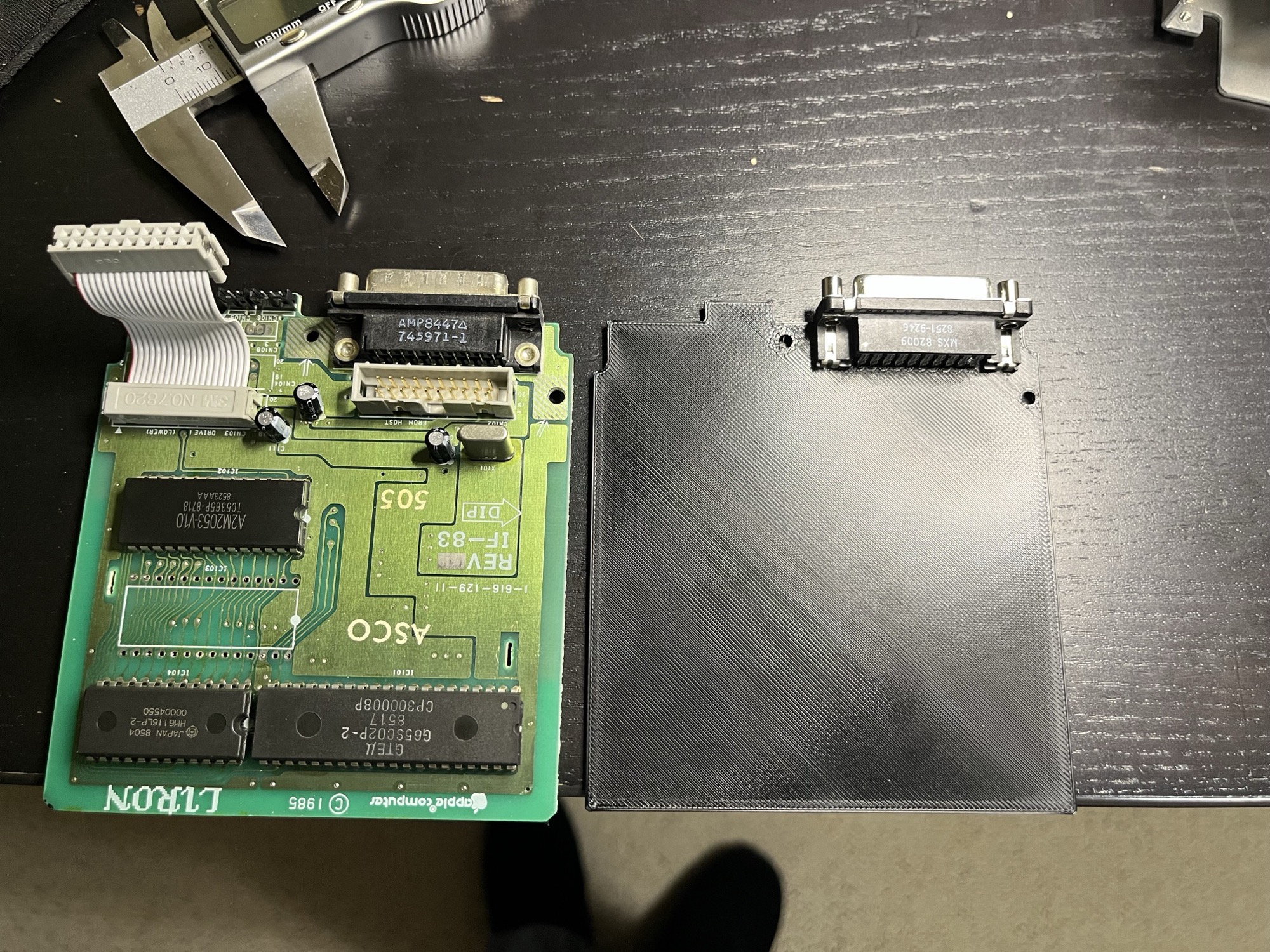
The steps were wrong in the last log
The two steps where the top section narrows aren’t what I had. Checked against the IF-83 again, the left one is 12 mm deep and the right one 6 mm (component side). I fixed the numbers in the last log and redrew the outline before printing.
Where it ended up
The connector faces the top edge of the narrow section. The end of its body is 3 mm from that section’s right edge.
| Hole | Position |
|---|---|
| Right board lock to the side mounting hole | 10.36 mm center to center |
| Left board lock to the mounting hole by the tab | 9.97 mm center to center |
My caliper guess for the first one was about 9 mm. The print says 10.36 is right.
Still open
- M8, the daisy chain, and M9 are still ahead on the bench.
- This is the board’s final shape. I don’t expect any more mounting holes or connectors to fit.
- Next is the real schematic.