M6: the Liron's first packet reaches my board
The host side of my board is back on the Apple, and it’s safe this time. The Liron card’s reset pulse and its first SmartPort command packet show up on the Pico’s inputs, and the packet decodes on the scope: sync, then C3 for packet begin. There’s no SmartPort firmware yet, so the IIe still says no device connected.
The breakouts have the rails on their own row
The homemade DB-19 adapter that put -12 V on /WRREQ is gone. I got two KingPow IDC20P-B boards, 2x10 IDC to screw terminals with a DIN rail mount. One is J1 for the host side. The other goes on the mechanism side, because my CN104 tap had the same problems.
My DB-19 to IDC20 cable is wired like the cable inside a UniDisk. DB-19 pin n goes to flat pin 2n-1 for pins 1 to 9, pins 11 to 19 go to the even side, and ACK (DB-19 pin 10) goes to flat pin 20. Flat 19 has no wire. I had ACK on 19 in my notes from the old adapter and caught it before wiring.
That interleave puts GND and every Apple rail on the odd row of terminals and the signals on the even row. The -12 V is on J1.9 and /WRREQ is on J1.10, a whole terminal row apart. My board runs off the bench supply, so the rail terminals stay empty.
| J1 | DB-19 | Signal | Shifter |
|---|---|---|---|
| 1, 3, 5, 7 | 1-4 | GND | - |
| 2, 4, 6, 8 | 11-14 | PH0-PH3 | U1 B1-B4 |
| 9 | 5 | -12V | empty |
| 10 | 15 | /WRREQ | U1 B5 |
| 11 | 6 | +5V | empty |
| 13, 15 | 7, 8 | +12V | empty |
| 14 | 17 | /HSTEN | U1 B6 |
| 16 | 18 | RD | U3 B1 |
| 18 | 19 | WR | U1 B7 |
| 19 | - | no wire | - |
| 20 | 10 | ACK | U3 B2 |
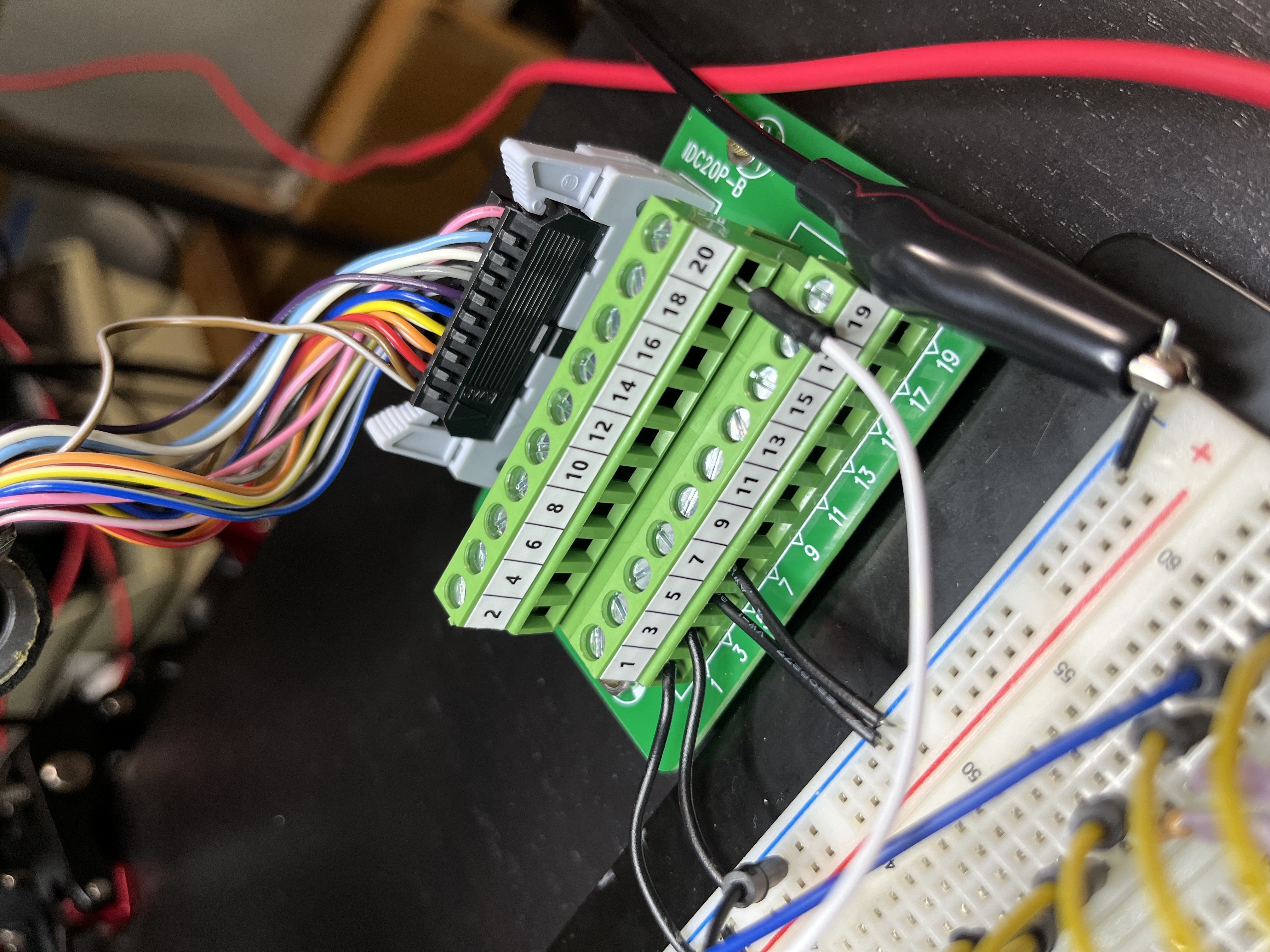
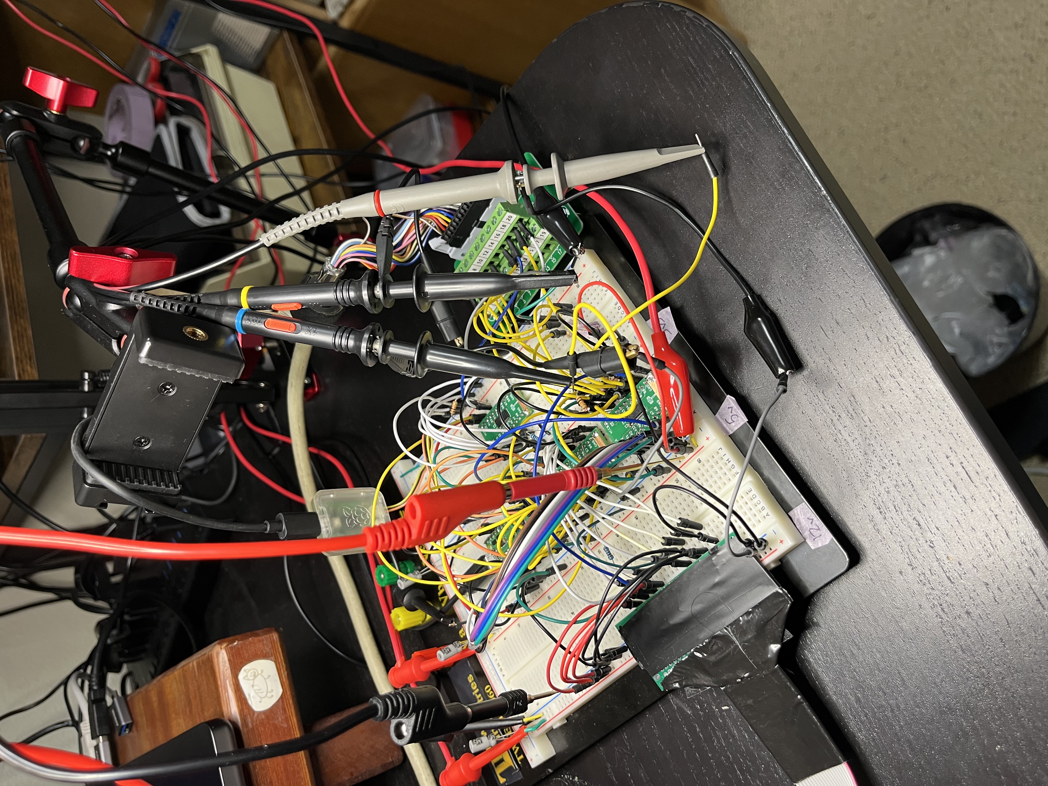
Before any power I beeped every signal from the DB-19 pin to its shifter pin, then every Apple rail against every other pin, the bench +5 and the 3.3 V rail. Everything that should connect beeped and nothing else did.
The bench supply can’t read small currents
On the first power-up the bench +5 went into current limit at 10 mA and sat at 1.43 V. The mechanism was still hanging off the bench +5 through the old CN104 tap, and its logic draws tens of mA on +5 alone. I unplugged it.
With the mechanism off, the supply still showed 30 mA. A DMM in series with each shifter’s VCCB read 0.04 mA per board, so the supply’s readout is just off at that end. Its 0.01 A limit also kicks in well under 10 mA. For anything this small I use the DMM now, and 0.05 A is the lowest limit I trust.
First connect, Pico unplugged
With the Pico unplugged both shifters sit in Hi-Z, so this checks the rails and idle levels with nothing of mine driving. The current stayed at 0.04 mA when the IIe came on.
| J1 | Signal | Measured |
|---|---|---|
| 9 | -12V | -12.16 V |
| 11 | +5V | 4.73 V |
| 13, 15 | +12V | 12.38 V |
| 2, 4, 6, 8 | PH0-PH3 | about 40 mV, moving |
| 10 | /WRREQ | 5.15 V |
| 14 | /HSTEN | 5.15 V |
| 16 | RD | 4.67 V |
| 18 | WR | 3.56 V |
| 20 | ACK | 4.88 V |
/WRREQ and /HSTEN read 5.15 V because the bench was set to 5.15 V and they have 10k pull-ups to it. I dropped the bench to 5.00 V. U3 drives RD and ACK at its VCCB, and that shouldn’t sit 0.4 V above the 4.73 V the Liron runs on.
Reading the host lines over SWD
Next the Pico went on with the M5 firmware, which holds U3’s /OE high so RD and ACK stay off the bus. I read the GPIO input register over SWD without halting. The first read had PH2 high and PH3 low while J1 showed the opposite. My jumpers were shifted by one at the Pico header. After fixing that the Pico matched J1.
Then I sampled the inputs for 25 s, about 4,000 reads a second, while I typed PR#5:
| GP2-GP8 | Reads | What it is |
|---|---|---|
| 0x1e8 | 99491 | idle, PH1 + PH3 |
| 0x1d4 | 321 | PH0 + PH2, SmartPort reset |
| 0x1c0 | 42 | all phases low |
| 0x1ec | 1 | REQ (PH0) + PH1 + PH3 |
| 0x1ac | 1 | REQ with /WRREQ low, the host sending a packet |
My pull-up holds ACK high, so the Liron thinks a device is ready and starts sending.
WR idled under the shifter’s threshold
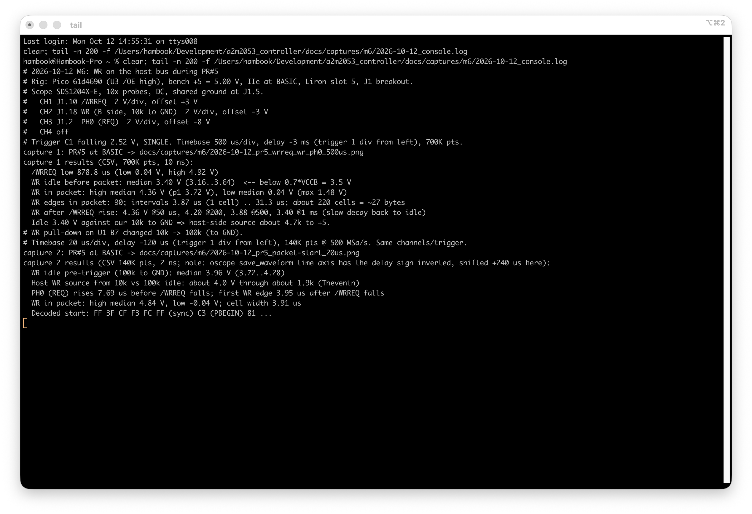
WR measured 3.56 V idle on the meter, and the SN74LVC8T245 only guarantees a high above 0.7 x VCCB, 3.5 V at 5 V. So I put it on the scope during PR#5: /WRREQ, WR and PH0 (REQ), triggered on /WRREQ falling.
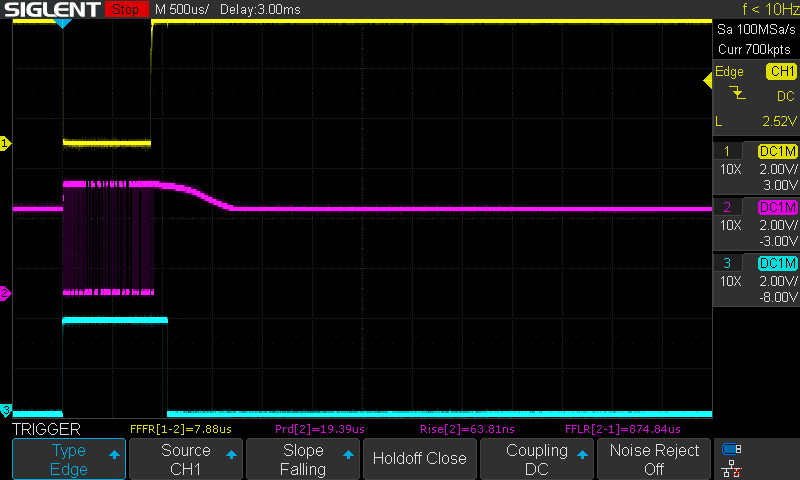
During the packet WR swings 0.04 V to 4.36 V, which is fine. Idle it sat at 3.40 V with about 0.25 V of noise, under the threshold. The cause was my own 10k pull-down on U1 B7. I swapped it for a 100k and idle came up to 3.96 V. Working back from the two idle levels, the Liron drives idle WR at about 4.0 V through about 1.9k, so 4.0 V is as high as it goes.
If you’re level-shifting a Liron card’s WR with an LVC8T245 at 5 V, keep the pull-down weak. The card idles WR at about 4.0 V through about 1.9k, and a 10k pull-down drags it to 3.4 V, under the 3.5 V input-high.
| 10k pull-down | 100k pull-down | |
|---|---|---|
| WR idle | 3.40 V (3.16-3.64) | 3.96 V (3.72-4.28) |
| WR high in packet | 4.36 V | 4.84 V |
| /WRREQ low | 879 us |
The packet
Zoomed in at 20 us/div, REQ comes up 7.7 us before /WRREQ drops, and the first WR edge is 3.95 us after that. The cells are 3.91 us, which is the IWM’s 7.16 MHz divided by 28. Taking each transition as a 1, the start decodes to:
FF 3F CF F3 FC FF   sync
C3                  packet begin
81                  destination ...
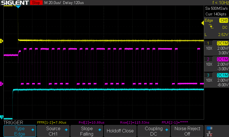
It looked very familiar from the Byte Hamr days. Those sync bytes are also the same self-sync pattern the drive writes as its track preamble, which my board already writes from M5.
Still open
- Put the mechanism side on the second breakout, with short heavy +5 V and GND runs, and check the read scan at 5.0 V.
- Write the M6 spec: the FM receiver, the ACK handshake, and what the RAM disk holds.
- WR has about 0.5 V of margin at idle now. Watch it once the receiver is running.
- Re-format disk 2 with my board.