M1: the mechanism answers
The Pico now talks to the mechanism. A USB console sets the address lines, reads RD, and prints all 16 status bits. The first status came back as an 800K double-sided drive, disk-in and write-protect follow the disk the way the docs say, and RD settles 27-35 ns after an address change. Nothing moved yet. Motor, stepping and eject are M2.
The first status line
oe on enables the shifter, enbl on selects the drive, status walks all 16 addresses. No disk:
STATUS DIRTN=0 CSTIN=1 STEP=1 WRPROT=0 MOTORON=1 TK0=0 SWITCHED=0 TACH=0 RDDATA0=0 RDDATA1=0 SUPERDRIVE=0 REG_B=0 SIDES=1 READY=1 DRVIN=0 REVISED=1
DRVIN=0, SIDES=1, REVISED=1 and SUPERDRIVE=0 are the 800K double-sided signature from the tashnotes drive table. MOTORON=1 means the motor is off, since most of these bits are active low.
Disk and write-protect
| State | CSTIN | WRPROT | TK0 |
|---|---|---|---|
| No disk | 1 | 0 | 0 |
| Disk in, hole covered | 0 | 1 | 1 |
| Disk in, hole open | 0 | 0 | 1 |
WRPROT 0 means protected, and it also reads 0 with no disk. I had the tab backwards on the first insert and called it protected when it was write-enabled. Flipping it sorted that out.
The mechanism spun the motor for about half a second on its own when the disk went in. The console was sitting idle, so that’s the drive seating the hub by itself.
TK0 read 0 before the first insert and 1 after. Either the head moved during the insert or TK0 reads differently with a disk loaded. M2’s recal will tell me where the head actually is.
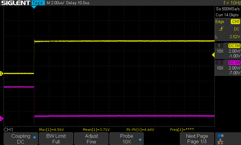
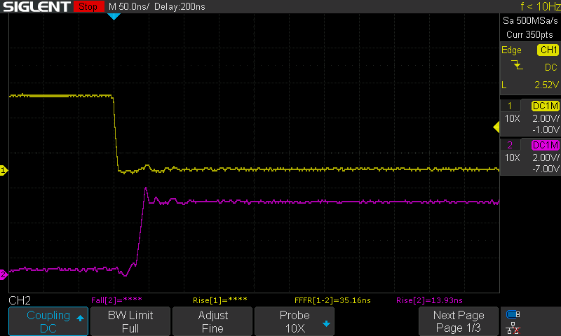
RD settles in about 30 ns
The firmware waits 10 us after changing the address before it samples RD. I wanted to know how much of that is needed. status 12 (SIDES, reads 1) and status 14 (DRVIN, reads 0) differ only in CA0, so flipping between them toggles RD with or without a disk in.
| Edge | Delay | Edges |
|---|---|---|
| CA0 rise to RD fall | 27 ns (scope measurement) | 6.8 ns / 8.2 ns |
| CA0 fall to RD rise | 35.2 ns (scope measurement) | 5.5 ns / 13.9 ns |
RD is driven hard in both directions, so the 4.9k pull-up I found on the mechanism in M0 isn’t doing the rising edge. 10 us is about 300 times longer than needed. It stays for now, and M4 can cut it to 1 us.
What the reviews caught before flashing
The M1 firmware is two pieces: the mechanism sequences behind a small bus interface, unit-tested on the Mac against a fake bus, and the console plus the real GPIO bus. Each piece got its own review, then one more over the whole branch. Three of the bugs they found were in code I’d written into the plan myself.
motor onwaits up to 2 s for READY. On a timeout it reported “not ready” and left the motor spinning. It now sends MOTOR_OFF before it gives up.- The console kept the first 79 characters of a longer line and ran them, so
motor onwith junk after it would still start the motor. A long line now getsERR line too longand nothing runs. - My bench step for the settle time put the scope on CA0 while toggling
status 1andstatus 0. Those two addresses differ only in SEL, so CA0 would never have moved. That’s why the measurement above uses 12 and 14.
The READY timeout after a seek also went from 0.5 s to 1 s. The ERS gives 500 ms as the worst case, so the old value had no margin at all. The console also echoes and handles backspace now, since screen showed nothing while typing.
| Suite | Checks |
|---|---|
| mechanism sequences | 75 |
| console parser | 33 |
| CRC-32 | 3 |
A compile-time assert also checks that the bus mask can’t include GP18, the write gate. Nothing in M0 to M3 is allowed to write a disk.
Power rule
M0 showed the shifter puts a 5 V strobe on LSTRB when the Pico’s 3V3 ramps. Back then /ENBL was always high and the drive ignored it. Now the firmware can hold /ENBL low. So it’s enbl off, oe off, mechanism supply off, and only then touch the Pico’s USB. SWD flashing and resets are fine.
Still open
- Where the head sits after a disk insert.
- M2: motor on and tach, step, recal, seek, eject. First time the firmware moves anything.