M0: the strobe on every power edge
The bench rig is up. A Pico 2 talks to the Sony 800K mechanism out of one of the dead-board drives through two SN74LVC8T245 boards. The scaffold firmware is flashed and answers on USB. A reset over SWD leaves the mechanism lines alone. Pulling the Pico’s USB with the mechanism powered does not: the shifter drives LSTRB to 5 V for about 1.5 ms. The mechanism shrugs it off because /ENBL never goes low, but that margin is thinner than I’d like.
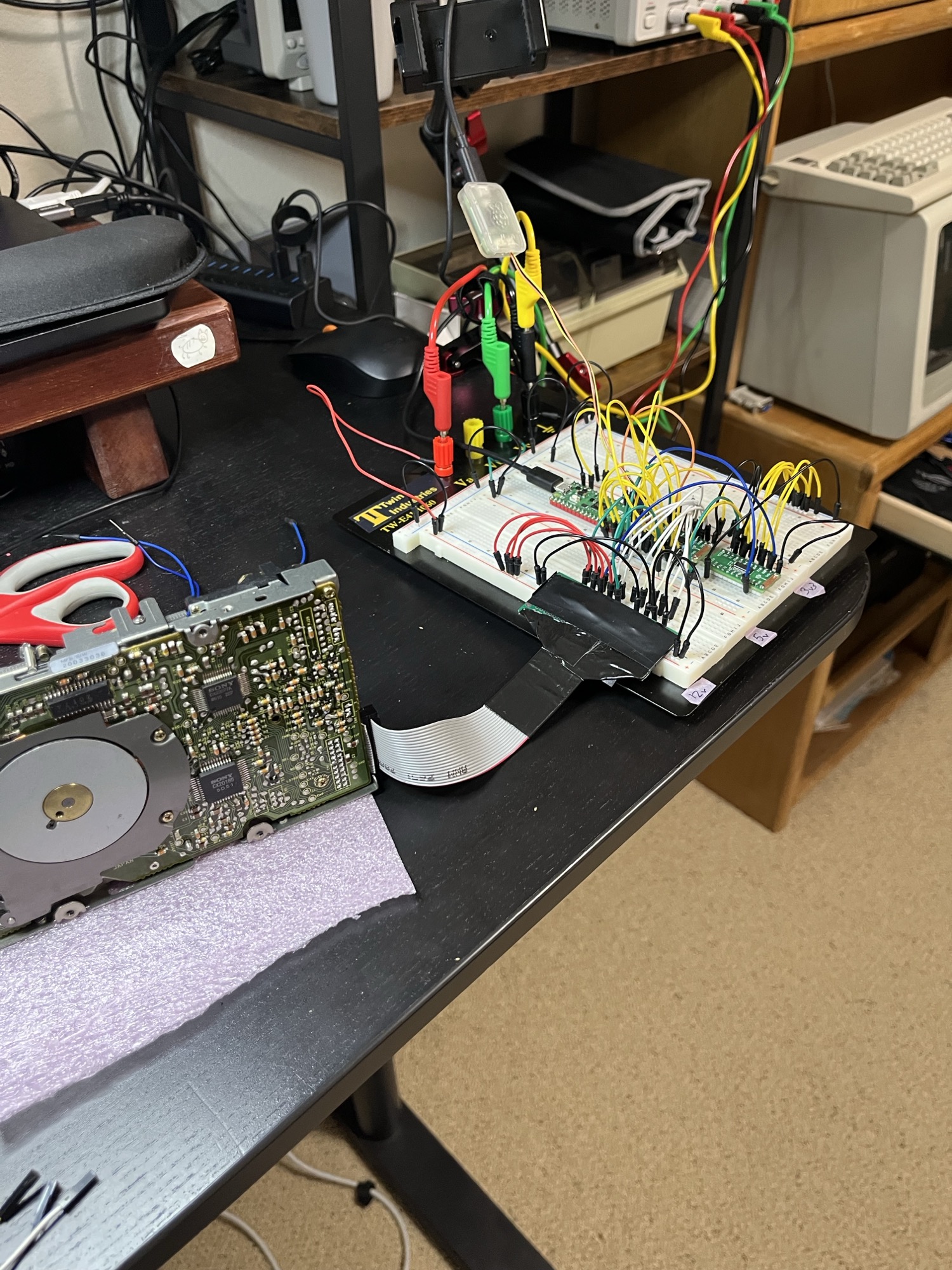
LSTRB fires when the Pico loses power
I’d assumed the 8T245’s /OE pin plus a 10k pull-up would keep the mechanism side quiet through anything the Pico does. That holds for a reset, where 3V3 stays up. It doesn’t hold while 3V3 itself is ramping.
When I unplugged USB, the Pico’s 3V3 fell to about 1.3 V in 3 ms and then sagged. Around 0.8 V the shifter woke up and drove LSTRB and CA1 to a full 5 V for about 1.5 ms. Plugging back in did the same thing for about 1.3 us as 3V3 came up through roughly 1 V.
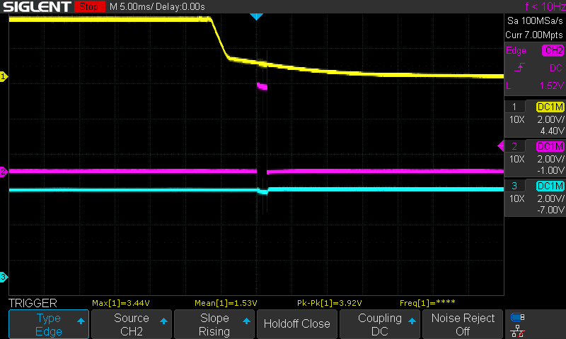
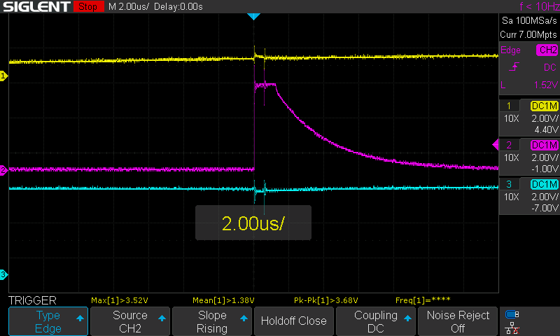
If you’re using an 8T245 with one rail already up, the outputs aren’t guaranteed Hi-Z while the other rail is between 0 V and its 1.65 V minimum. /OE doesn’t help there. The isolation in the datasheet is for a supply sitting at 0 V.
LSTRB is the line the mechanism latches commands on, so a stray rising edge could step the head or eject the disk. It didn’t, because commands only count while /ENBL is low, and /ENBL has its own 10k to +5V. On the unplug it dipped to 3.64 V. That’s fine for a TTL input and only just over 3.5 V if the CX23077A has CMOS inputs, which I don’t know.
| Event | LSTRB | /ENBL min | Mechanism |
|---|---|---|---|
| SWD reset (x3) | quiet | 5 V | silent |
| USB unplug (x2) | 5 V for ~1.5 ms | 3.64 V | silent |
| USB replug | 5 V for ~1.3 us | 4.76 V | silent |
For now the bench rule is mechanism supply off before I touch the Pico’s USB. On the real board 3V3 comes off the host’s +5V, so the two rails fall together and this mostly goes away. I still want a 3V3 supervisor holding the shifters off before this turns into a PCB.
Reset is clean
The plan’s actual M0 test passed. With the mechanism powered, I armed the scope on a falling edge of the shifter /OE, then a rising edge on LSTRB, then on CA1, with one make reset each. None of them triggered, and the Pico’s USB port re-enumerated every time, so the resets really happened. /OE sat at 3.21 V with about 400 mV of noise on it.
Wiring and power came up first try
I beeped out the 20-pin mechanism header before powering anything: pin 1 to GND, pin 8 to the LSTRB test point, pin 11 to 5VF. No shorts between rails. Pin 16 (RD) read 3.3k to +5V instead of 10k, which is my 10k in parallel with about 4.9k that lives on the mechanism.
With the Pico unplugged and the mechanism powered on its own:
| Rail | Limit | Idle current | At the connector |
|---|---|---|---|
| +5V | 1.0 A | 0.01 A | 4.90 V |
| +12V | 1.5 A | 0.00 A | 11.94 V |
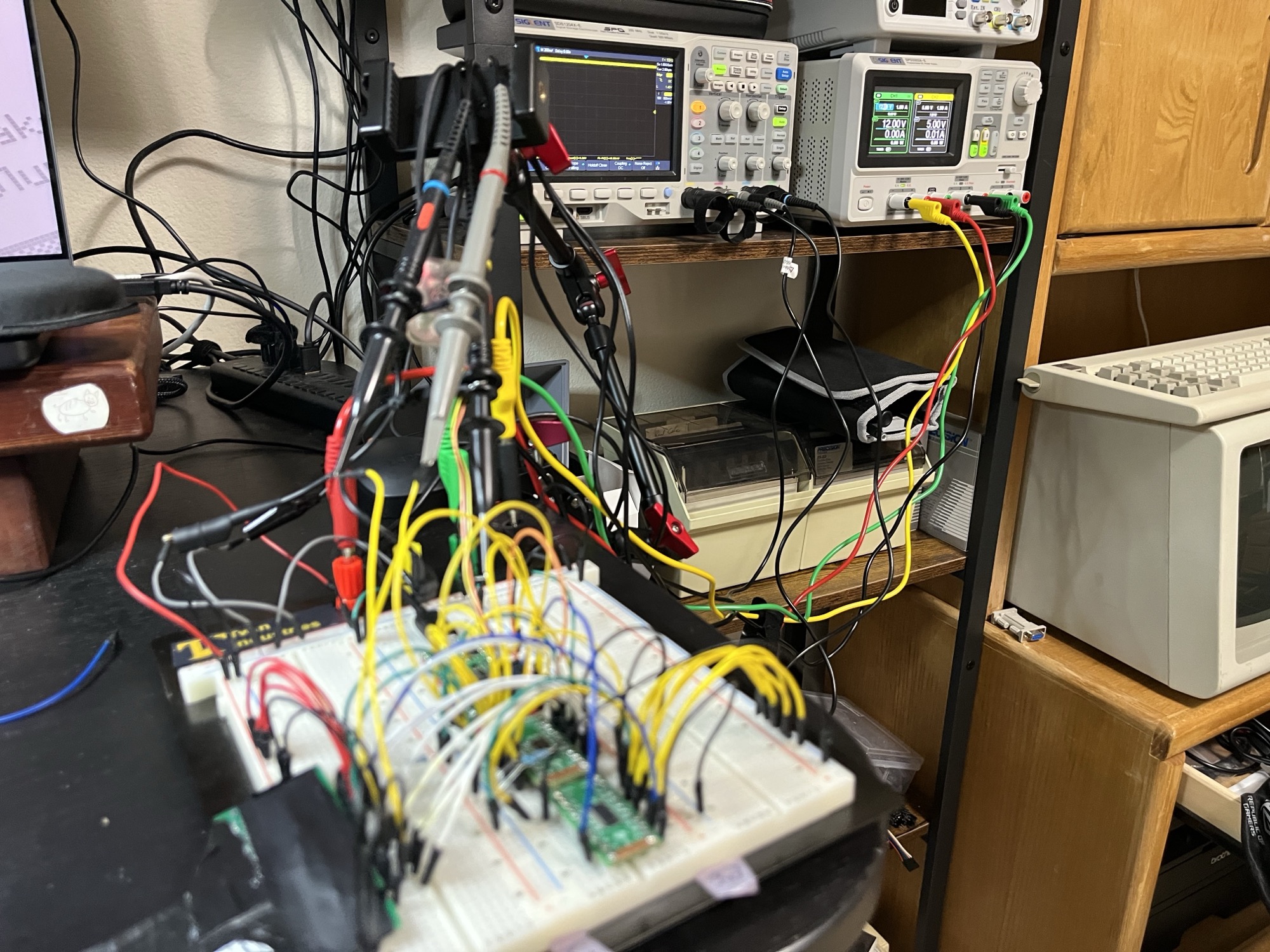
The supply says 5.00 V and the connector says 4.90 V, so 0.1 V goes missing in the leads and breadboard at only 10 mA. I want to know where before the motor starts pulling real current.
The firmware flashed over SWD on the first go with Raspberry Pi’s OpenOCD and a Debug Probe, and the console prints OK a2m_bringup (scaffold).
Still open
- What kind of inputs the CX23077A has. That decides how much the 3.64 V /ENBL dip matters.
- Which supervisor goes on the final board, and whether it also covers U4 for the daisy chain.
- Whether the mechanism tri-states RD when /ENBL is high or just leans on that 4.9k pull-up.
- The scope sampled at 10 MSa/s for the reset runs, so a glitch under about 100 ns could have slipped past.
- Where the 0.1 V on the +5V lead goes.
- Next is M1: read the mechanism’s status bits over the console.