Program counter: four '193s, worked on first power-up
Backfilled from a post on embedded.greygiant.com dated 2025-07-31.
What I tried
The 16-bit program counter. Four 74LS193s cascaded through their carry and borrow pins, so it counts up, counts down and loads a preset. 74LS245s on both sides: one pair to load a value in off the bus, one pair to put the count out on the bus, with the enables coming from the control word. A 74LS02 does the inversions the ‘193 wants.
Two passes at the schematic. The first had a 74LS32 OR in the PC_MUX decode; the control word already produced that state, so it came out. The second pass also fixed the DIR pins on the output transceivers, which I’d had backwards.
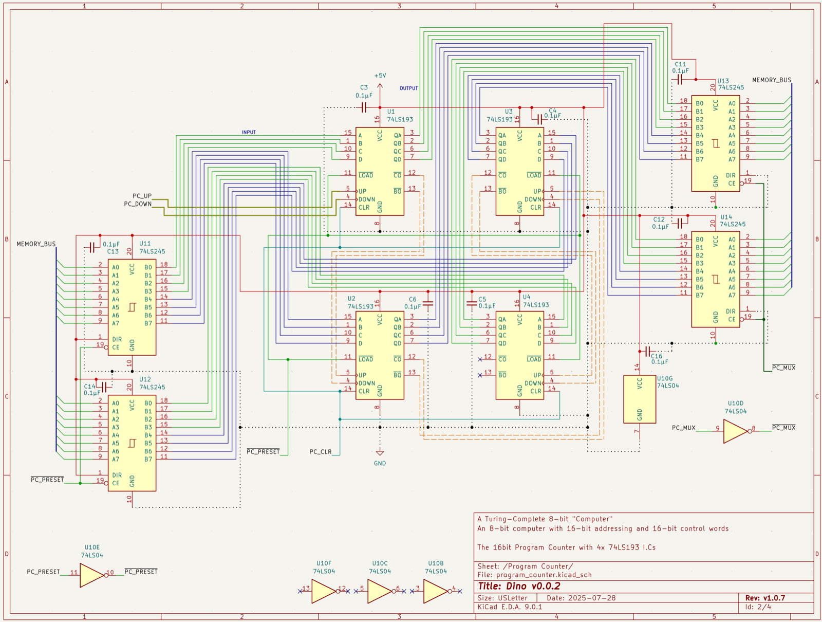
Before wiring I wrote down what a pass looks like: preset loads, increment carries across all four stages, decrement borrows across all four, PC_MUX turns the output transceivers on and off, the counter keeps counting with its outputs disabled, and it covers the full 16 bits.
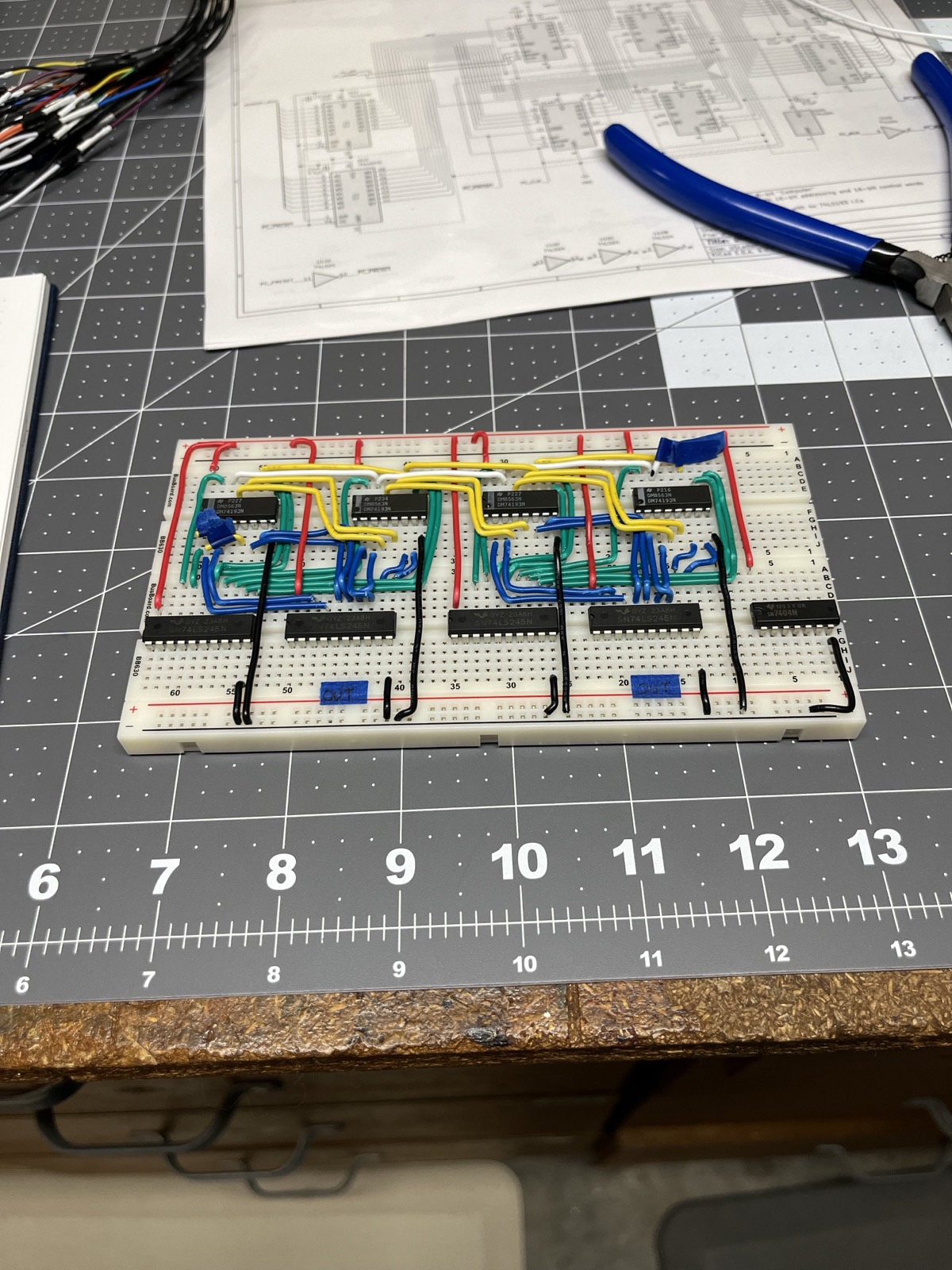
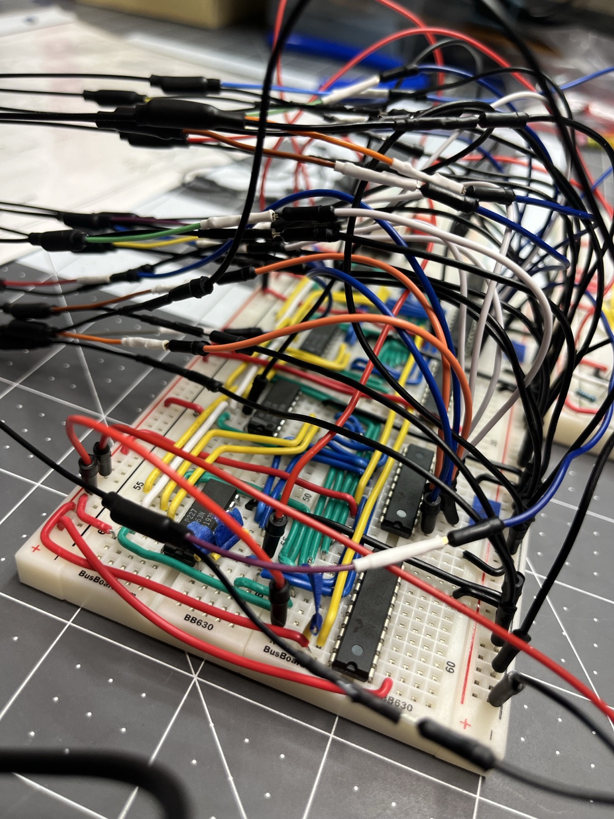
Wiring: I pre-fitted Dupont jumpers to find routing conflicts before cutting solid wire. Putting the input and output transceivers in alternating order meant every cascade stage was wired identically.
What I measured
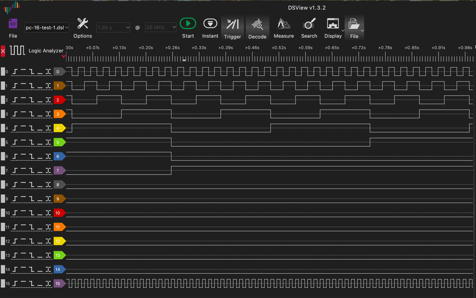
All 16 bits on the LA. It counted on the first power-up. Carry and borrow ripple through all four stages, no glitches on the bus at this clock.
What broke or surprised me
- Pushing the up and down inputs by hand didn’t cascade. The pulse off a button isn’t long enough for ~CO and ~BO to do their job into the next stage. Clocking it off the 555 at 60 Hz, it cascaded fine. The carry chain needs the pulse to stay low for a while after the edge.
- Preset didn’t load. I tested the high bits first because they’re easy to see on the LEDs. The input transceivers had been wired straight through during assembly, so they were never off. One connection fixed it.
Next
The T0 and T1 decoders for the universal fetch: ROM to IR under the PC’s address, then IR plus ring counter state forming the microcode ROM address. That’s the bootstrap, so the machine fetches its first instruction without anyone touching a switch.