A case for Rev 1.0, in 19 glued pieces
The Rev 1.0 boards are at PCBWay, so I designed the box they go in. It’s 359.6 x 288 x 115.6 mm, printed on a Prusa Core One in 19 pieces, glued and doweled. After that comes Bondo, sanding, more Bondo, and paint. Nothing is printed yet.
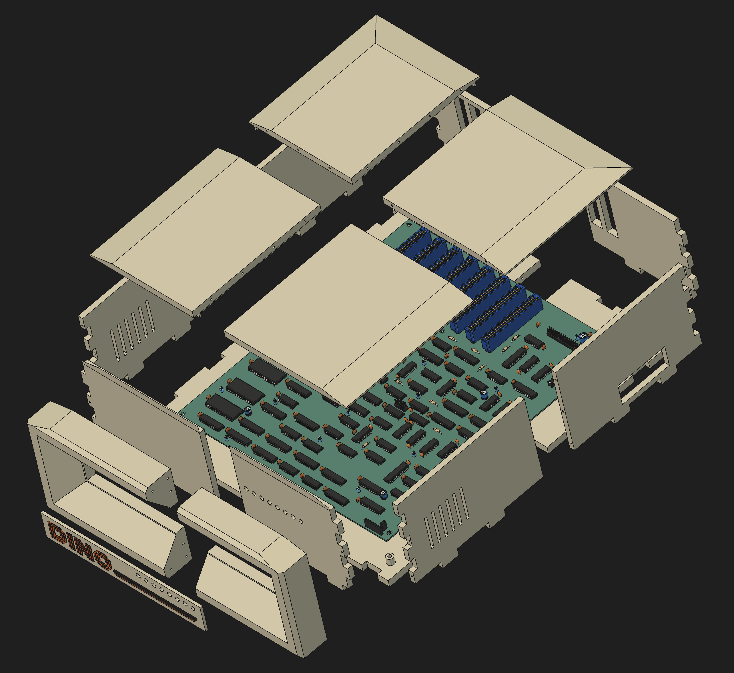
The case is a Python script (build123d) that reads the KiCad PCB for the outline, the five mounting holes, the eight card slots and the power header. If the board moves, the case moves with it. FreeCAD watches the output folder and reloads every piece when the script runs, so I check each change there before calling it done.
The front is a car grille
I started from a photo of a 70s Alfa Romeo nose and a sketch of my own.
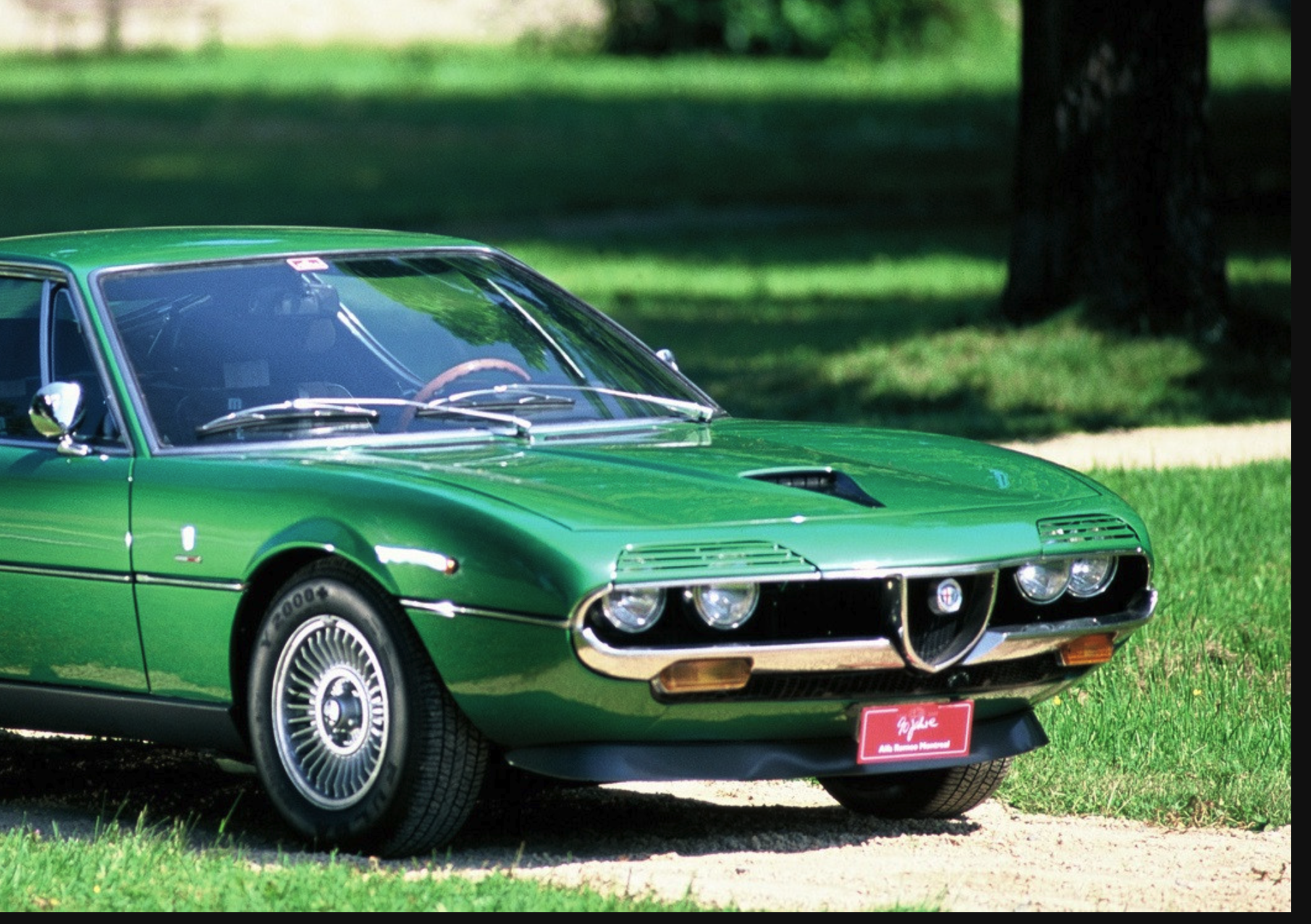
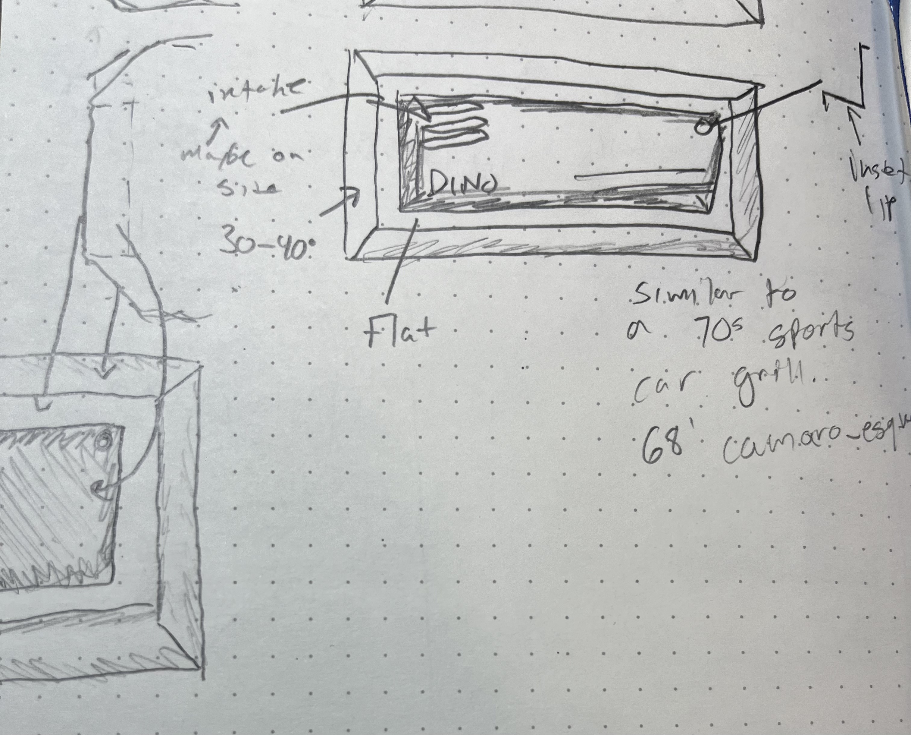
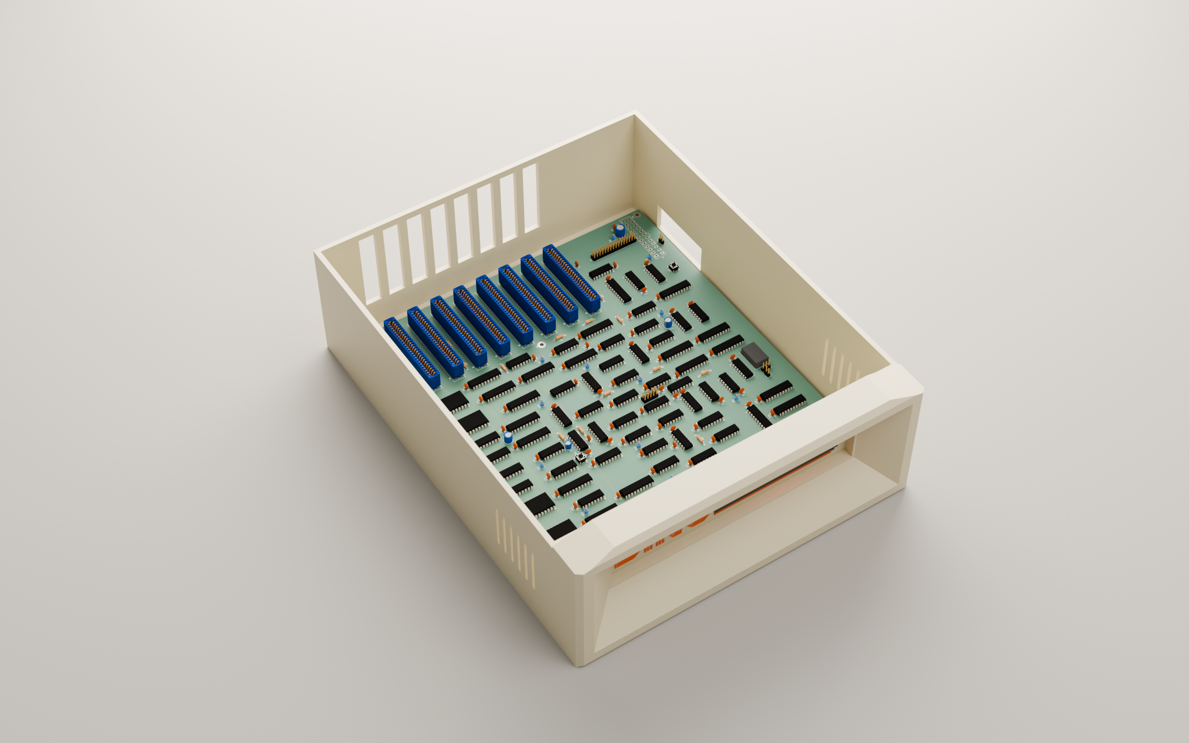
The front is a picture frame on all four sides: a flat rim, a bevel going in, a small ledge, a square step, then the recessed panel. The first pass looked like a drawer front, so it got deeper and steeper.
| Front frame | |
|---|---|
| Depth, face to the wall | 33 mm |
| Flat rim | 14 mm |
| Bevel | 40 deg to the face, 22 mm deep |
| Ledge | 2 mm |
| Step | 8 mm |
| Outer edge chamfer | 4 mm at 45 deg |
The cards come out the back, IBM PC style, one cutout per slot. Each side wall has six tall round-ended intake slots toward the front, 3 x 40 mm at 9 mm pitch, after the Apple IIe. The lid sits flush with the frame at the front and has a long shallow bevel down the sides and the back, 6 mm over 30 mm, about 11 deg.
The front panel is the brand
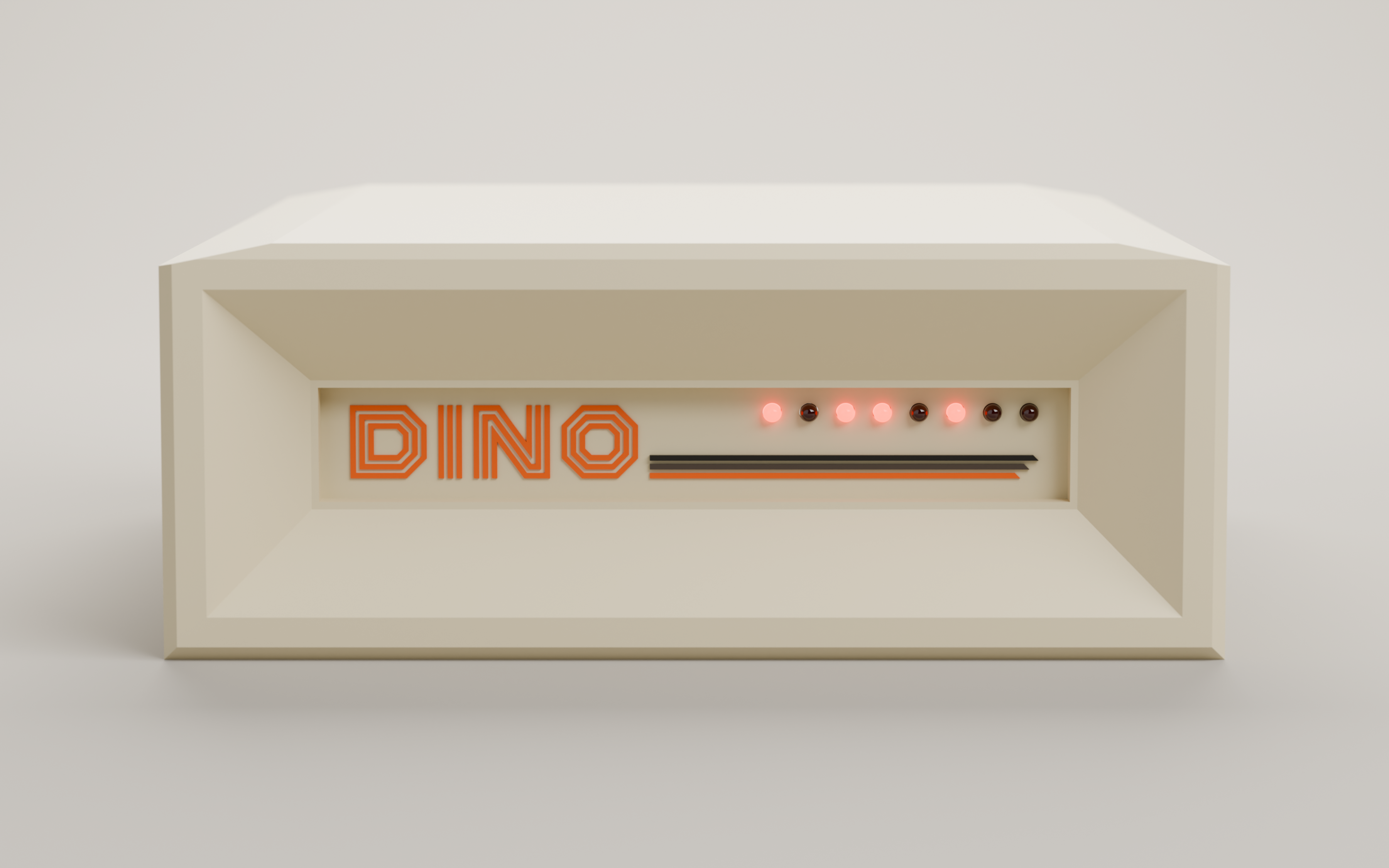
The front panel is the DINO wordmark, three raised bus lines (orange 0.6 mm, grey 1.0 mm, black 1.4 mm) and the eight OB LEDs, 5 mm reds in 5.2 mm bores at 10 mm pitch. The script reads the panel straight from the brand SVG, so nothing is retyped.
The LEDs sit top right. The last one ends where the black line (the longest one) ends, and it sits as far from the right edge as the D sits from the left.
Renders in Blender, with the board
KiCad exports the whole board with its 3D models and colors as one glTF, and Blender drops it on the standoffs:
kicad-cli pcb export glb --subst-models --include-tracks --include-pads \
  --include-zones --include-silkscreen --include-soldermask -o board.glb dino_v0_0_2.kicad_pcb
That’s 97 MB and about 40 s to export, so it gets done once and reused. Cycles on the Mac GPU renders the hero, front, rear and lid-off views. In the lid-off view the eight card sockets line up under the back cutouts. The renders show the case before it was parted.
Parting it for the printer
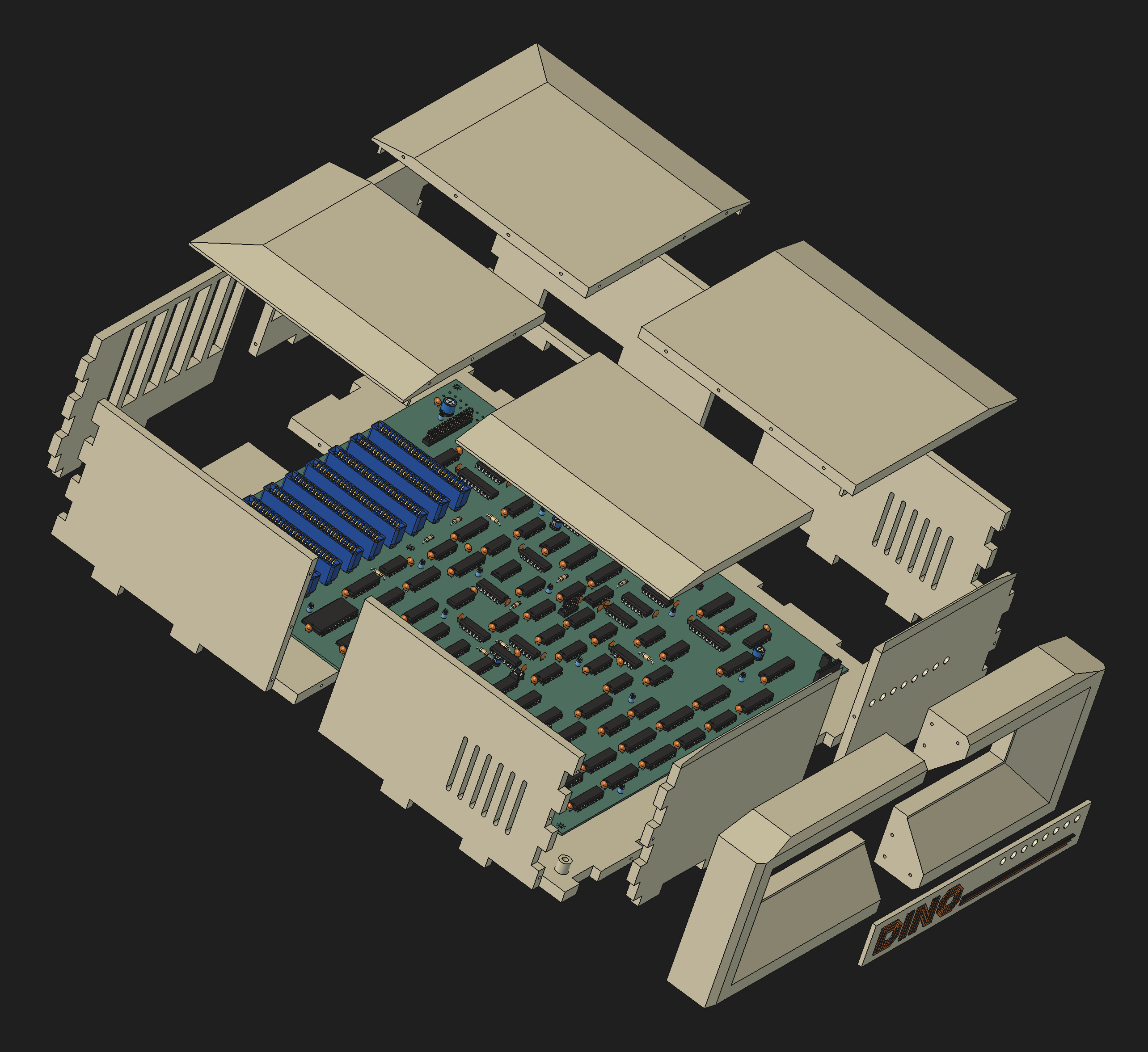
Every piece has to fit a 250 x 220 mm bed, and nothing on this computer is hollow. The first parting cut the tray into four corners, each a floor plus two walls standing up. That’s a big, tall, risky print, and the vents and the ATX hole would print with flat unsupported tops. So the tray is flat panels now, each printed lying down.
| Piece | Count | Size (mm) | Prints |
|---|---|---|---|
| Floor quarters | 4 | 163 x 133-156 x 8, standoffs on top | underside down |
| Side wall halves | 4 | 163 x 108 x 6 | outside down |
| Back wall halves | 2 | 133-156 x 108 x 6 | outside down |
| Front wall halves | 2 | 133-156 x 108 x 6 | outside down |
| Lid quarters | 4 | 163 x 133-156 x 13 | roof down |
| Front frame halves | 2 | 133-156 x 116 x 33 | face up |
| Brand plate | 1 | 203.56 x 31.16 x 3 | face up |
The walls were 4 mm, which leaves 1 mm of plastic each side of a 2 mm dowel hole. A dowel can’t cross a 90 deg corner in a 4 mm wall at all, because it comes out the other side. The walls are 6 mm now. The corners are box joints: each corner column is cut into seven bands, alternating between the side wall and the back or front wall, so the walls interlock and square themselves. The walls stand on the floor, with 20 mm tabs that go down through slots in it. Dowels (1.75 mm filament in 2.0 mm holes, 8 mm each side) go only where a seam runs along a panel’s own plane: the wall halves, the floor quarters, the frame to the tray, and the frame halves to each other.
The frame prints face up, with its back on the bed, so the 40 deg bevel never overhangs. The same goes for the brand plate, and face up also means the logo colors can be swapped by layer height. The plate sits in a seat with a 0.2 mm glue gap, and the frame is 3 mm deeper so the step still shows 8 mm. With the thicker walls I widened the rim from 12 to 14 mm, which keeps the plate at exactly the brand panel’s size.
Open threads
- It reads as an 80s machine. I want it more 70s: walnut side cheeks, an earth-tone body, chrome LED bezels, maybe real RESET, RUN/STEP and clock-speed controls on the front. Parked for now.
- Lid: print roof up or roof down, and whether the lip is printed on or glued on as strips.
- Color swaps by height leave the grey and black lines orange for their first 0.6 mm. Live with it, or use a multi-material unit.
- Material (PLA, PETG or ASA) and infill aren’t picked. Nothing is sliced, so I don’t have a filament number yet.
- Untested fits: the 0.4 mm lid lip gap, the 2.0 mm dowel holes, the 4.0 mm heat-set insert holes, and the box-joint fingers. A test corner print comes first.
- The socket standing height is a guess (10 mm) until the boards arrive and I measure a Sullins socket. The clearance over the cards depends on it.
- The renders show the case before it was parted, so they need redoing.