Rev 1 boards arrive with both protection diodes backwards
What I tried
The first Rev 1 boards arrived this week. Initial power-up failed. Both protection diodes were installed backwards. I flipped them and went through bring-up with the validation gateware loaded.
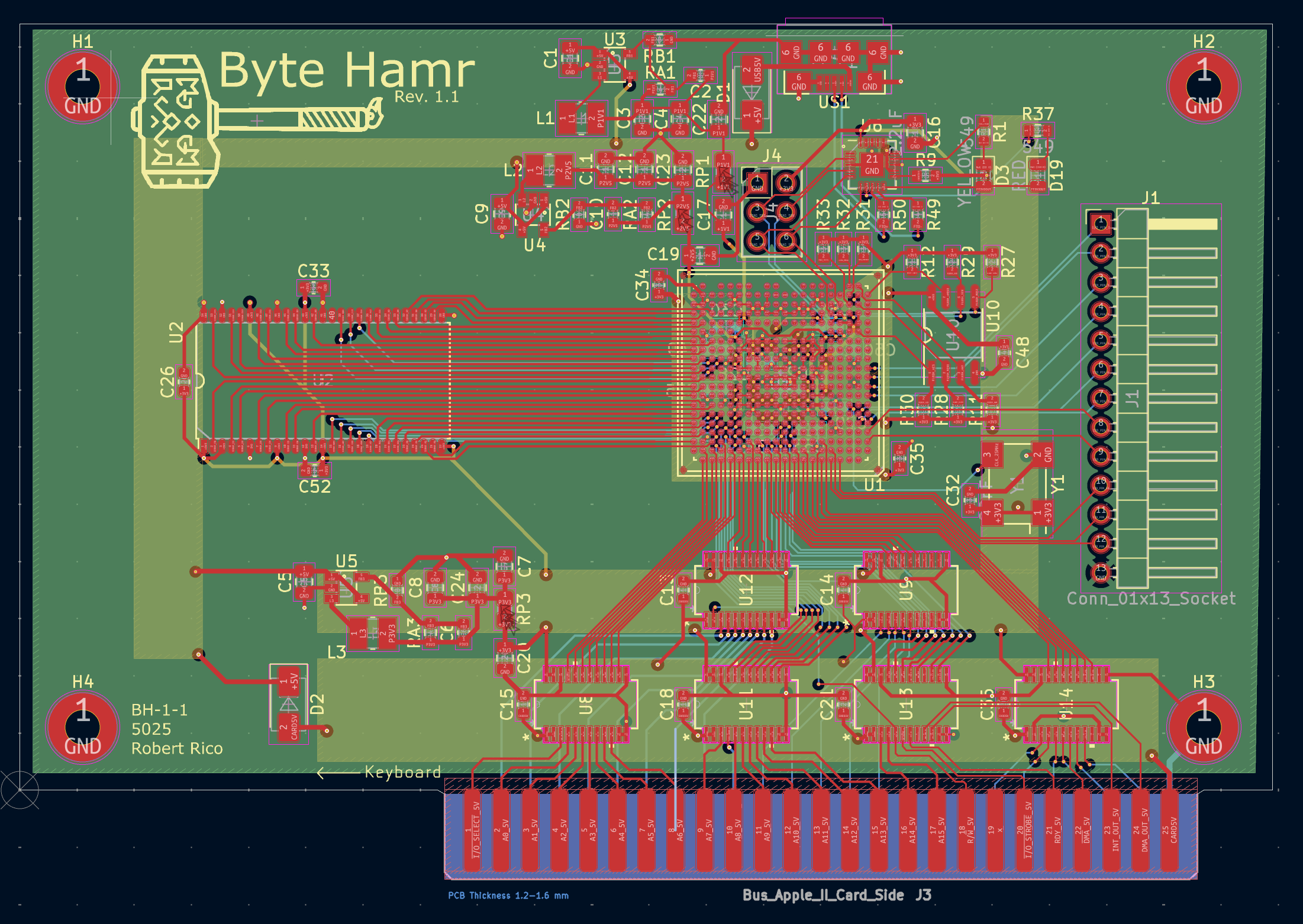
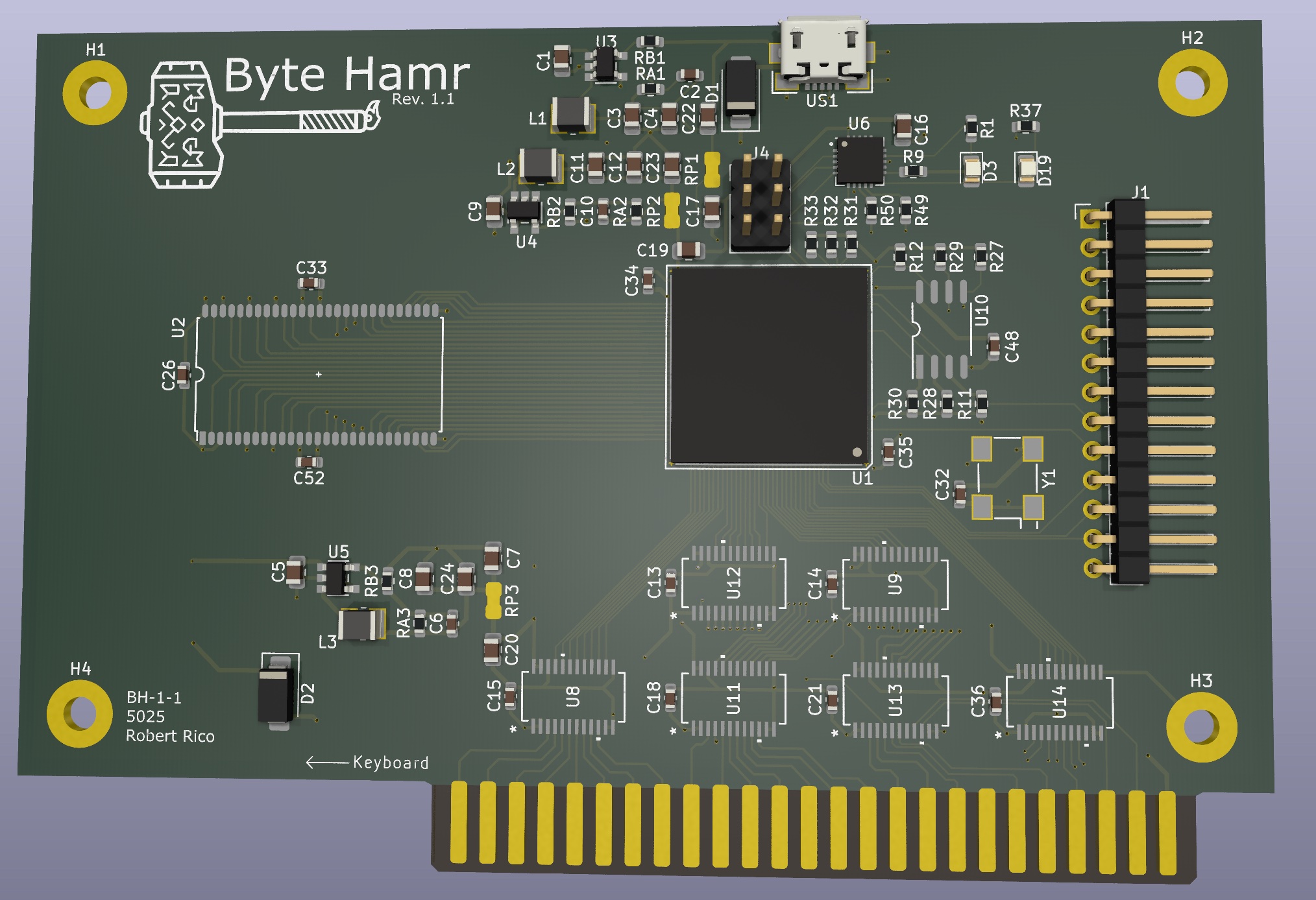
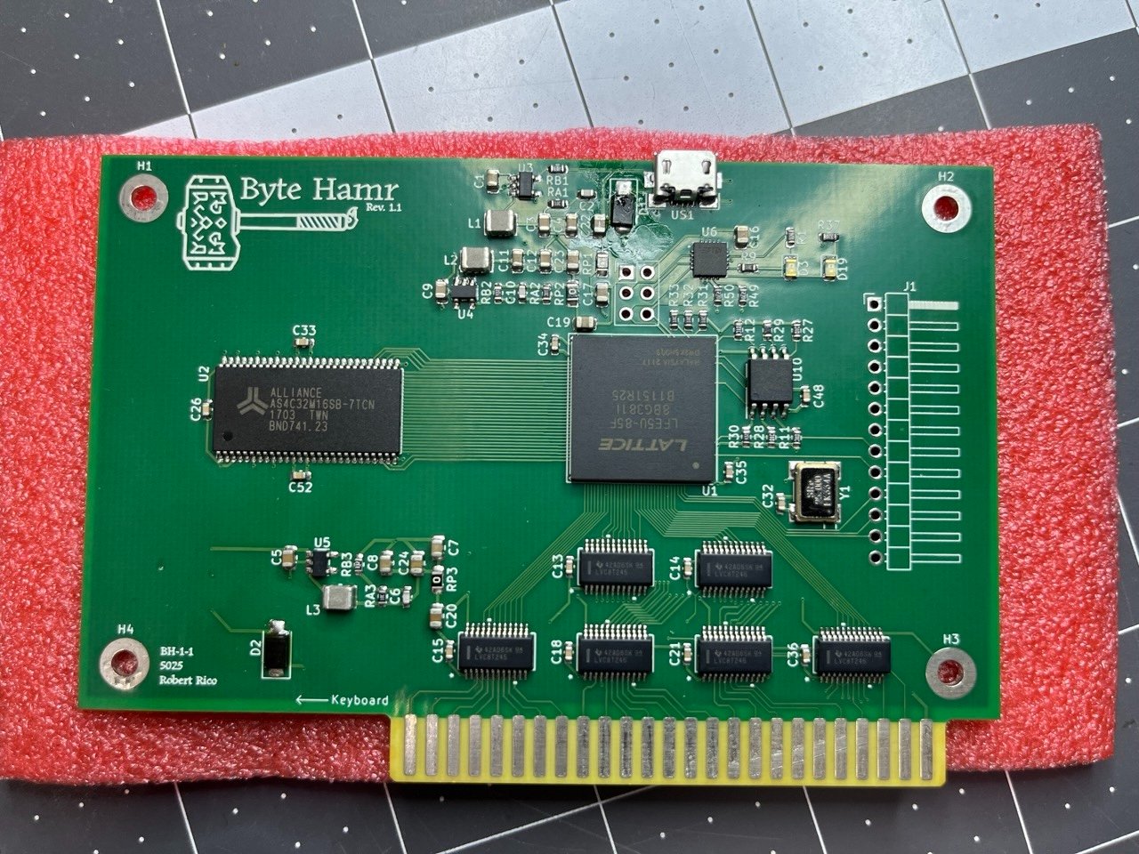
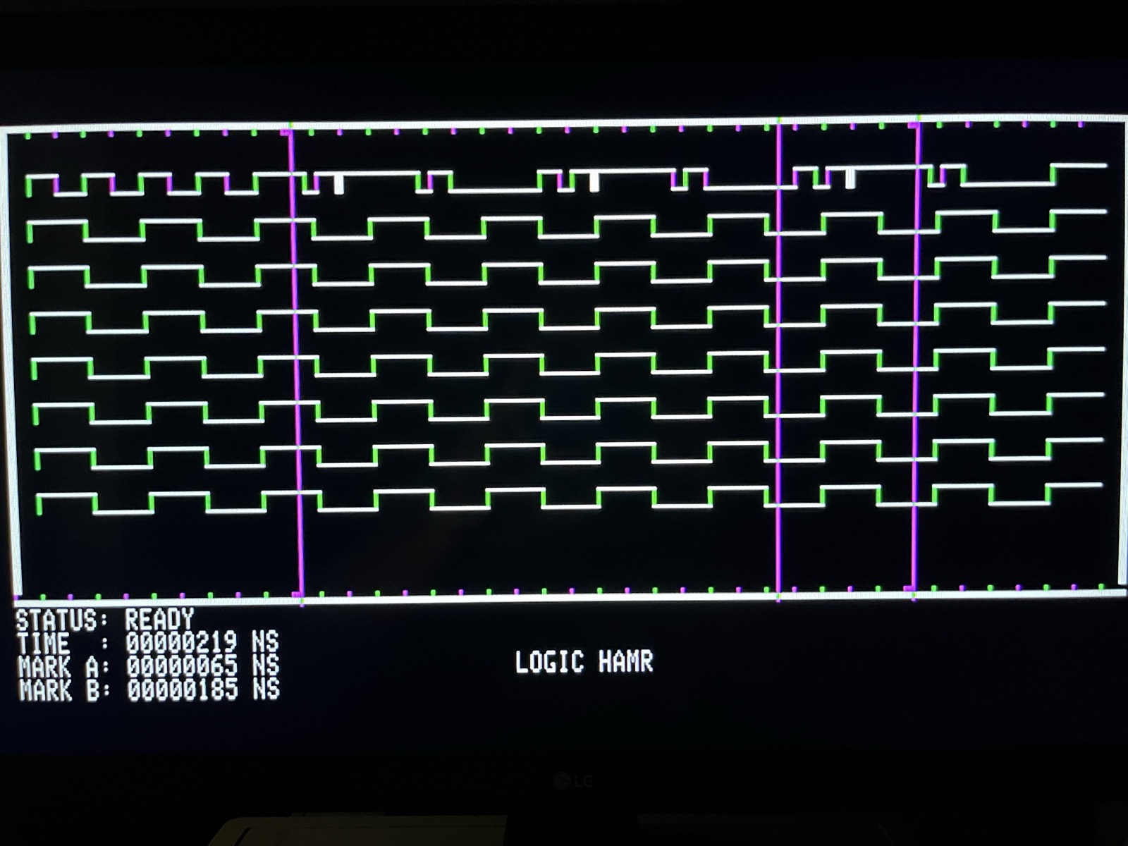
The first real project is a logic analyzer: 8 channels, 2 MHz sample rate, the 64 MB SDRAM as the capture buffer, waveforms drawn on the IIe in HIRES. The FPGA captures, stores, decimates and does the math. The IIe sends scroll and zoom commands and draws what it is handed.
I am building it from both ends at once. The IIe side is 6502 in Merlin Pro on the IIe itself: 8-channel waveform rendering on HIRES, cursor movement by pixel and by column skip, A and B markers with a time delta, zoom controls. It runs against mock data for now. The FPGA side has the bus interface validated with the signal_check gateware and GPIO responding to /IOSEL and /IOSTROBE. The SDRAM controller is next, then the capture engine. When the two halves meet, the IIe software talks to real hardware instead of test patterns.
What I measured
- 3.3 V, 2.5 V and 1.1 V rails all present after the diode rework.
- USB enumerates. JTAG programs the part.
- FPGA runs: 250 kHz heartbeat on the scope.
- Level shifters pass.
- Apple IIe bus interface and SDRAM: not yet tested in the machine.
What broke or surprised me
Two diodes backwards on my second PCB design ever. Woops.
Next
Put it in the IIe and check that the slot I/O addresses respond. I expect to write some assembly to prove every pin does what the schematic says. The target demo for the analyzer is a button debounce: press once, watch it bounce dozens of times on screen.