An idle Byte Hamr blocks every other card's interrupts
With two Rev 2 cards in the machine, neither one can interrupt the 6502. Both cards pulling the line low together works fine. The cause is U14, the 74LVC8T245 that carries the card’s IRQ, NMI, INH, RES and DMA out to the slot. Its OE and DIR pins are tied to ground, so it always drives the slot side push-pull. When the RTL “releases” a line, U14 drives it high. Those are wired-OR lines on the Apple bus, and everything else on them expects open-collector.
I found it shopping for ‘245s
U12 to U14 (SN74LVC8T245DBQR) are out of stock, and what stock is out there runs about 5x the price. The SN74LVCH8T245DBQR is a drop-in: same package and pinout, plus bus hold, and no shifter I/O on the board has a pull resistor for the bus hold to fight. While checking that, I read U14’s wiring properly for the first time. The FPGA side is always the input, OE is always on, and nothing in the RTL can change that.
Ctrl-Reset has always worked, and a Super Serial Card never gave me trouble, so I wanted it measured before I believed it.
A test that runs itself from the slot ROM
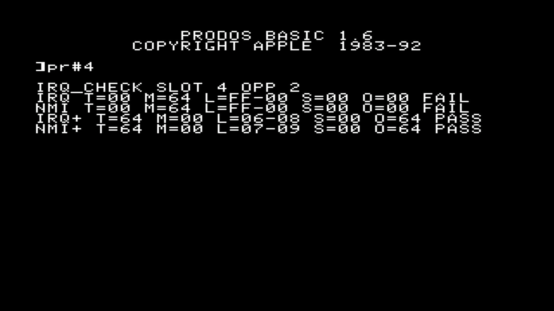
irq_check goes on both cards, same bitstream. The card you PR# is the tester, and the other one sits idle with its U14 holding the lines high. The 6502 is the sensor. The fabric watches the address bus for vector fetches ($FFFE for IRQ, $FFFA for NMI), fires 100 shots about 2 ms apart, and counts how many get taken.
I didn’t want to type a monitor program in, so the bitstream carries a 512-byte slot ROM. It finds its own slot, copies itself to $1000, finds the other card by a signature in its ROM, and prints the results. It works in any slot, which mattered, since my cards are in 4 and 2, not 4 and 5 like I’d assumed.
Pulling a card out of the IIe is a lot more work than flashing one, so the baseline is built in. After the single-card runs, it tells the other card to pull the same line at the same time. Those are the + lines.
IRQ_CHECK SLOT 4 OPP 2
IRQ T=00 M=64 L=FF-00 S=00 O=00 FAIL
NMI T=00 M=64 L=FF-00 S=00 O=00 FAIL
IRQ+ T=64 M=00 L=06-08 S=00 O=64 PASS
NMI+ T=64 M=00 L=07-09 S=00 O=64 PASS
| Field | Meaning |
|---|---|
| T | interrupts taken (hex, $64 = 100) |
| M | missed |
| L | min-max latency in PHI0 cycles |
| S | this card’s spurious vector fetches |
| O | the other card’s count |
One card pulling against an idle card got 0 taken for both IRQ and NMI. With both pulling, it was 100 of 100 at 6 to 9 cycles of latency, and the other card saw every fetch too. That clears the card’s output path, the ROM and the handler, and leaves U14 on the idle card. S=00 on the + lines says the line only fell once both cards were pulling. An earlier run from slot 2, before the + lines existed, failed the same way.
Why a resistor or the RTL can’t fix a push-pull output
U14 sources and sinks 32 mA at 5 V.
| Fix | What happens |
|---|---|
| Pull-up | nothing, the line is already driven high |
| Pull-down | has to be under about 150 ohms to win, which holds IRQ asserted forever |
| 1k in series | my low against the motherboard pull-up lands at about 1.2 V, over the 6502’s 0.8 V |
| RTL | the FPGA only sets U14’s input; 0 drives low, 1 drives high, Z reads as 1 |
| OE or DIR to an FPGA pin | one enable for all seven channels, so asserting IRQ also drives NMI/INH/DMA high, and it’s a 0.635 mm pin lift |
The FPGA can’t even see IRQ or NMI. Those nets only touch U14 and the edge finger.
The bodge is a Schottky on 2 mm of trace
A series Schottky, cathode toward U14, makes the line open-drain. U14 can pull it to about 0.4 V, and when U14 goes high the diode blocks it and the motherboard pull-up owns the line.
The spot is on the back of the board. Each line goes U14 pin, top-side stub, via, then down the back to its edge finger. Everything at U14 is 0.635 mm pitch, so not there. The run from the IRQ via to the top of the finger is about 2.1 mm, and the finger top sits 0.4 mm above the card-edge shoulder. A SOD-523 Schottky (RB751S40 or BAT54XV2) fits between the via and the finger. The other way is Kynar from the via to a diode glued down somewhere roomy, and back to a scraped bit of trace above the finger.
IRQ and NMI are the ones that matter. DMA and INH only matter with a card that uses them, and RES already works. Every card that can sit idle needs it, which means both of mine. The full write-up is in hardware/byte_hamr/rev2_errata.md in the repo.
What Rev 3 would need
Rev 3 may never happen, but if it does:
- INH, RES, IRQ, NMI and DMA on a 74LVC07A: open-drain, 5.5 V tolerant outputs, runs from 3.3 V.
- RDY as an output, on the LVC07A’s sixth gate, so the card can stretch cycles.
- Input shifter channels on IRQ and NMI, so the FPGA can see who’s holding a line.
- The INT and DMA daisy chain stays push-pull on something like a 74AHCT1G125.
- DMA itself still needs DIR and OE on the address ‘245s and an R/W output.
That also means fewer of the ‘245s that are hard to buy.
Still open
- No bodge yet. The first one goes on the slot 2 card’s IRQ only. With that,
PR#4should show IRQ PASS and NMI still FAIL. - With the bodge on, I need to meter IRQ with the card idle. It should sit near 5 V from the motherboard pull-up. If it floats, there’s no pull-up on that line.
PR#2hasn’t been run with the+lines.- RES still fights U14 on every reset. It works, but I haven’t measured it.
- I’m reading the 8T245’s DIR and OE as referenced to VCCA, and I haven’t checked that against the datasheet.